 .
..
.


.
.
.
.
.
.
.
.
.
.
.
.
.
.
.
.
.
.
.
.
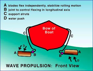
The arrows in the bare-bones diagram show the vertical push of the water, the function is caused by the wave or by strong current, acting on a stern-mounted rigid blade.
Simplifying the representation to stern-mounted blades only, this illustration shows the response of the system to the surface waves.
In fact, this design calls for an additional set of propulsive blades to be mounted well forward on both sides of the hull. In this top-view illustration, graduated tone is used to indicate a flexible-blade system.
The forward and aft blades function independently. When one is pushed down by the waves, the other is forced up. Similarly, the blades on each side of the boat are also free to respond differently as wave forces shift.
Thirty degrees of deviation from level is acceptable, but not over 45 degrees. The curved line indicates a "quadrant" which is a structure to limit motion inward so that the blade would not rub against the hull. As an alternative, some form of hydraulic system might be designed to enable control over the degree of tilt while eliminating this external structural detail. To achieve a more hydrodynamic shape, the goal of design refinement is to minimize the number of exterior-mounted connecting parts which can become fouled with seaweed or other debris.
.
(LOOK AT THE DIAGRAMS!)
The diagram shows support struts with a control joint restricting the amount of motion permitted. Flexible blades might not require this type of joint; in that case, the degree of flex would be that permitted by the material used.
In addition to propulsion, this method of capturing and redirecting the energy into forward motion would theoretically mitigate the infamous up-down, pitching and rolling motions that cause to sea-sickness.
--yuwei
edited and reviewed by: seokting on 17/06/08
No comments:
Post a Comment